
Test : Integrity of the bridge
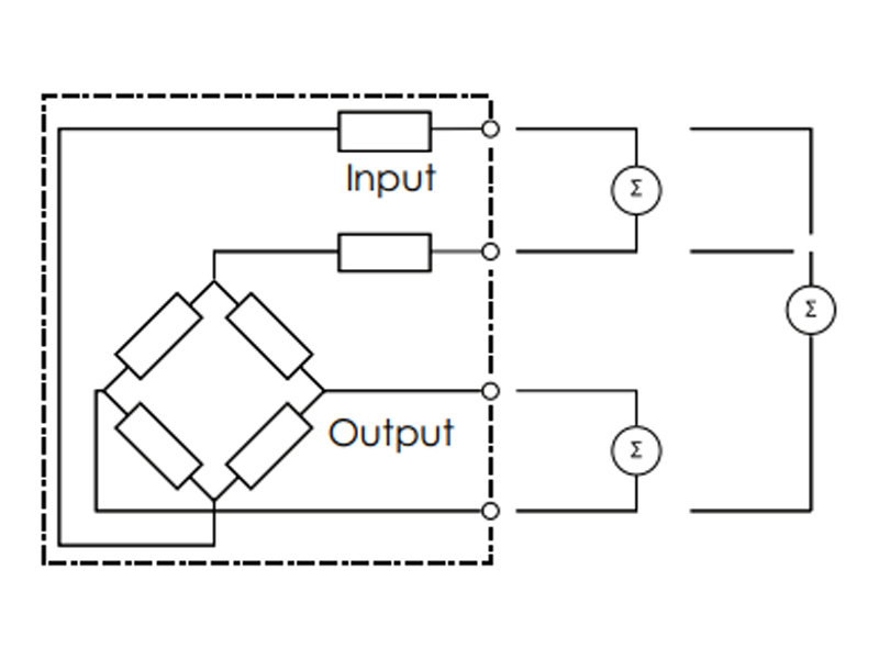
Verify bridge integrity by measuring input and output resistance and bridge balance. Disconnect the load cell from the junction box or measuring device.
Input and output resistances are measured with an ohmmeter on each pair of input and output leads. Compare the input and output resistances to the original calibration certificate (if available) or data sheet specifications.
Bridge balance is obtained by comparing the –output to –input and –output to +input resistances. The difference between the two values should be less than or equal to 1Ω.
Analyze:
Changes in bridge resistance or bridge balance are usually caused by disconnected or burned wires, faulty electrical components, or internal short circuits. This can be caused by overvoltage (lightning or welding), physical damage from shock, vibration or fatigue, excessive temperature or inconsistent production.
Test : Impact Resistance
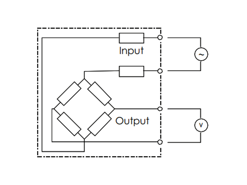
The load cell should be connected to a stable power source, preferably a load cell indicator with an excitation voltage of at least 10 volts. Disconnect all other load cells of a multiple load cell system.
Connect a voltmeter to the output leads and tap the load cell lightly with a mallet to vibrate slightly. When testing the shock resistance of low capacity load cells, extreme care should be taken not to overload them.
Observe the readings during the test. The reading should not become erratic, it should remain reasonably stable and return to the original zero reading.
Analyze:
Erratic readings may indicate a faulty electrical connection or a damaged bondline between the strain gage and the component due to electrical transients.
Post time: Aug-30-2023