
Comparison of Strain Gauge Load Cell and Digital Capacitive Sensor Technology
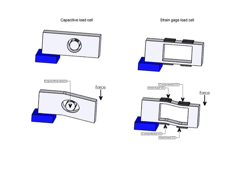
Both capacitive and strain gauge load cells rely on elastic elements that deform in response to the load to be measured.
The material of the elastic element is usually aluminum for low cost load cells and stainless steel for load cells in corrosive industrial applications.
Capacitive strain gauge sensors measure the deformation of the elastic elements individually, and the output of the sensors is converted by an electronic circuit into a signal representing the load.
A capacitive sensor is a conductor placed at a small distance from the elastic element and measures deformation without contact with the elastic element, while a strain gage is an insulating resistive foil bonded directly to the elastic element so that it is directly exposed In shocks and overloads, which are often encountered in industrial applications.
Sensitivity
Additionally, capacitive sensors are very sensitive, with a 10% change in capacitance, while foil strain gauges typically have only a 0.1% change in resistance. Since capacitive sensors are much more sensitive and therefore require much lower deformation of the elastic element, the strain on the elastic element of a capacitive load cell is 5 to 10 times lower than that of a strain gauge load cell.
Wiring and Sealing
The high change in capacitance helps provide a digital output signal, which in capacitive load cells is a high-speed signal that directly expresses the load in g, kg, or Newtons. A low-cost coaxial cable with a single-wire sealed connector powers the load cell and transmits a high-speed digital signal back to the instrument, which may be located hundreds of meters away. In a standard analog strain gauge load cell, the power supply and low level analog signal are usually conducted to the instrumentation via a rather expensive 6 wire cable where the analog signal is converted to digital. In a digital strain gauge load cell, the amplifier and A/D conversion are placed in the housing, and the power and digital signals are usually conducted to the instrumentation via fairly expensive 6 or 7 wire cables.
Post time: Aug-15-2023